

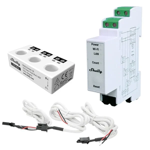
Main features
4 Quadrant measurement
DIN rail mounting
Multiple connection types: three phase or single phase installations
Current transformer connection: non contact measurements.
Phase sequence error detection1 (option)
Channel-to-channel calibration2
No load threshold3
Optical pulse indication of energy usage
Real-time clock: stored data keeps correct timestamps even if the internet connection is interrupted.4
Data logs: up to 60 days of data stored on the device for later retrieval
External contactor control: loads can be controlled based on device automation or scripts. Available with the addition of the Shelly 3EM Switch Add-on
Accuracy Class B (active energy)5
Photovoltaic ready
1 The Device has phase sequence error detection circuits. This detection works on phase voltages and considers only the zero crossings. The regular succession of these zero-crossing events is Phase A followed by Phase B followed by Phase C. If the sequence of zero-crossing events is, instead, Phase A followed by Phase C followed by Phase B, then a phase_sequence error is reported when the Phase sequence error detection option is enabled.
2 At least 500 W load is required for each channel.
3 In case the total load for the three channels drops below 30 VA per channel the measured power level will be displayed, but no consumed energy will be accumulated to the energy statistics and a No load threshold notification will be displayed in the Device web interface and the mobile application.
4 Shelly devices rely on internet connection for device clock. In case of installation network requirement or service interruption, the built-in clock provides correct timestamps for records.
5 The Device has a measurement accuracy of 1%, based on internal design validation and testing.
Use cases
Combined 3-phase current transformer (CT) that is designed to be mounted directly over a circuit breaker
Industrial Power Distribution:
In industrial settings with complex power distribution systems, a combined 3-phase CT mounted over a circuit breaker can efficiently measure and monitor current levels. This is crucial for optimizing energy usage and identifying potential issues in real-time.
Commercial Buildings and Facilities:
For commercial buildings and facilities, where space is often limited in electrical panels, the compact design of the CT is beneficial. Mounting it directly over circuit breakers allows for efficient use of space while ensuring accurate current measurement.
Motor Control Centers (MCCs):
Motor control centers, which are commonly found in manufacturing plants and industrial facilities, often have multiple circuit breakers. A combined 3-phase CT mounted over each breaker provides an integrated solution for monitoring motor currents, aiding in preventive maintenance and troubleshooting.
Data Centers:
In data centers, where precise monitoring of power consumption is crucial, combined 3-phase CTs can be installed over circuit breakers to measure the current flowing through critical equipment.
Renewable Energy Installations:
Combined 3-phase CTs can be used in renewable energy installations, such as solar or wind power systems. By mounting them directly over circuit breakers in the control panels, accurate current measurements can be obtained for monitoring and control purposes.
Substation Monitoring:
In electrical substations, where space is often at a premium, combined 3-phase CTs can be advantageous. Installing them directly over circuit breakers helps in monitoring the current levels in the different phases, contributing to the overall stability and reliability of the substation.
Building Management Systems (BMS):
For intelligent building management systems, having accurate real-time data on current consumption is essential. Combined 3-phase CTs can be installed over circuit breakers to provide the necessary information for energy management and demand response strategies.
Power Quality Monitoring:
In applications where maintaining power quality is critical, such as in sensitive electronic equipment or medical facilities, combined 3-phase CTs can be used to monitor current waveforms and identify any anomalies that might affect the quality of power supplied.
Electrical Panel Upgrades:
During electrical panel upgrades or retrofits, space constraints may arise. A combined 3-phase CT, designed for direct mounting over circuit breakers, offers a space-saving solution without compromising accurate current measurement.
Smart Grid Deployments:
In the context of smart grids, where real-time data is essential for grid management and optimization, combined 3-phase CTs can be deployed over circuit breakers to provide accurate current information for monitoring and control purposes.
In each of these use cases, the combined 3-phase CT offers a space-efficient and integrated solution for current measurement, contributing to the overall efficiency, safety, and reliability of the electrical systems.
Simplified internal schematics
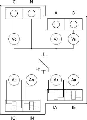
Device electrical interfaces
Inputs
4 line inputs on screw terminals: 3 L and 1 N
4 current transformer inputs: 3 for L current measurements and 1 for N current measurement
Ethernet port
1 RJ45 connector
⚠CAUTION! Plug in or unplug the LAN cable only when the Device is powered off! The LAN cable connector must not be metallic in the parts touched by the user to plug in or unplug the cable.
Add-on interface
Shelly proprietary serial interface
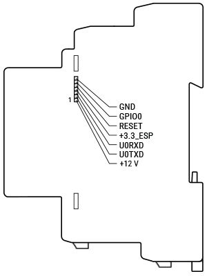
⚠CAUTION! High voltage on the add-on interface when the Device is powered!
Detailed inputs and outputs description
Connector to Shelly Pro 3EM-3CT63
three 2-pin MX3.0-2x1Y connectors
Inputs
6 current transformer line inputs on screw terminals: 3 for + current measurements and 3 for – current measurement
Connectivity
Ethernet
Wi-Fi
Bluetooth
Protocols
Modbus
MQTT
RPC
Safety function
Internal temperature sensing and reporting
Supported load types
Resistive (incandescent bulbs, heating devices)
Capacitive (LED light drivers, capacitor banks, electronic equipment, motor start capacitors)
Inductive (transformers, fans, refrigerators, air-conditioners)
User interface
Inputs
One tactile dome button
Press briefly to toggle the state of the relay in the attached Shelly Pro 3EM Switch Add-on.
Press and hold for 5 sec to activate Device AP.
Press and hold for 10 sec to factory reset.
Outputs
LED indication
Power: Red light if the power supply is connected.
Wi-Fi (varies):
Blue light if in AP mode.
Red light if in STA mode, and not connected to a Wi-Fi network.
Yellow light if in STA mode, and connected to a Wi-Fi network. Not connected to Shelly Cloud or Shelly Cloud disabled.
Green light if in STA mode, and connected to a Wi-Fi network and the Shelly Cloud.
The LED will be flashing Red/Blue if OTA update is in progress.
LAN: Green light if LAN is connected.
Count: Red light will be flashing when the Device is measuring energy according to settings with frequency dependent on the energy flowing through the measured circuit.
Specifications
Enlarges the table by opening it in a full screen dialog
Quantity | Value |
|---|---|
Physical | |
Size (HxWxD): |
|
Weight: |
|
Screw terminals max torque: | 0.4 Nm / 3.5 lbin |
Conductor cross section: |
|
Conductor stripped length: | 6 to 7 mm / 0.24 to 0.28 in |
Mounting: |
|
Conductor aperture Shelly 3CT63: | Ø9 mm / Ø0.35 in |
Shell material: | Plastic |
Shell color: | White |
Environmental | |
Ambient working temperature: | -20°C to 40°C / -5°F to 105°F |
Humidity: | 30% to 70% RH |
Max. altitude: | 2000 m / 6562 ft |
Electrical | |
Power supply: | 100-260 V~ 50/60 Hz |
Power consumption: | < 3 W |
External protection: | Tripping characteristic B or C, |
Shelly 3CT63 electrical strength: | 1000 V~, 60 sec |
Sensors, meters | |
Internal-temperature sensor: | Yes |
Voltmeter (AC): | 100 – 260 V |
Voltmeter accuracy: | ±1 % |
Ammeter (AC): | 0 – 63 A |
Ammeter accuracy: | ±1 % (2 – 63 A), ±2 % (1 – 2 A), ±5 % (0 – 1 A) |
Compatible current transformers: | 3CT63 |
Power and energy meters: |
|
Channel-to-channel calibration minimum load: | 500 W per channel |
No load threshold: | 30 VA per channel |
Measurement data storage: | At least 60 days of 1 min data resolution |
Data export: |
|
Radio | |
Wi-Fi | |
Protocol: | 802.11 b/g/n |
RF band: | 2400 – 2495 МHz |
Max. RF power: | < 20 dBm |
Range: | Up to 30 m / 100 ft indoors and 50 m / 160 ft outdoors |
Bluetooth | |
Protocol: | 4.2 |
RF band: | 2400 – 2483.5 MHz |
Max. RF power: | < 4 dBm |
Range: | Up to 10 m / 33 ft indoors and 30 m / 100 ft outdoors |
Microcontroller unit | |
CPU: | ESP32-D0WDQ6 |
Flash: | 16 MB |
Firmware capabilities | |
Webhooks (URL actions): | 20 with 5 URLs per hook |
Scripting: | Yes |
MQTT: | Yes |
Scripting: | Yes |
Encryption: | Yes |
Basic wiring diagrams
Enlarges the table by opening it in a full screen dialog
Fig. 1: Three-phase wiring diagram |
Fig. 2: Single-phase wiring diagram |
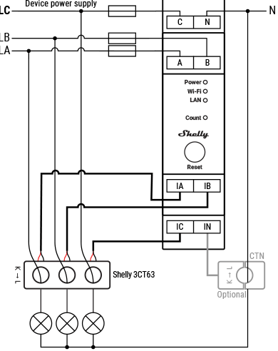
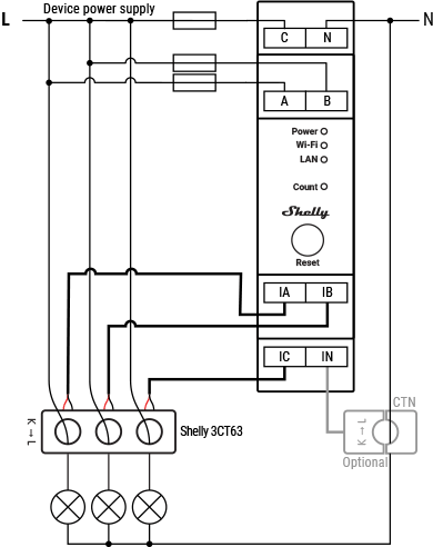
Legend
Enlarges the table by opening it in a full screen dialog
Terminals | Wires | ||
|---|---|---|---|
A: | Phase A terminal | LA: | Phase A live (110-240 V~) wire |
B: | Phase B terminal | LB: | Phase B live (110-240 V~) wire |
C: | Phase C terminal | LC: | Phase C live (110-240 V~) wire |
N: | Neutral terminal | N: | Neutral wire |
IA: | Phase A current transformer input | ||
IB: | Phase B current transformer input | ||
IC: | Phase C current transformer input | ||
IN: | Neutral current transformer input | ||
Current transformers | |||
3CT63: | 3-phase current transformer/63A | ||
CTN: | Neutral current transformer (optional, not included) | ||
K->L: | Direction of the primary current flow | ||
Installation
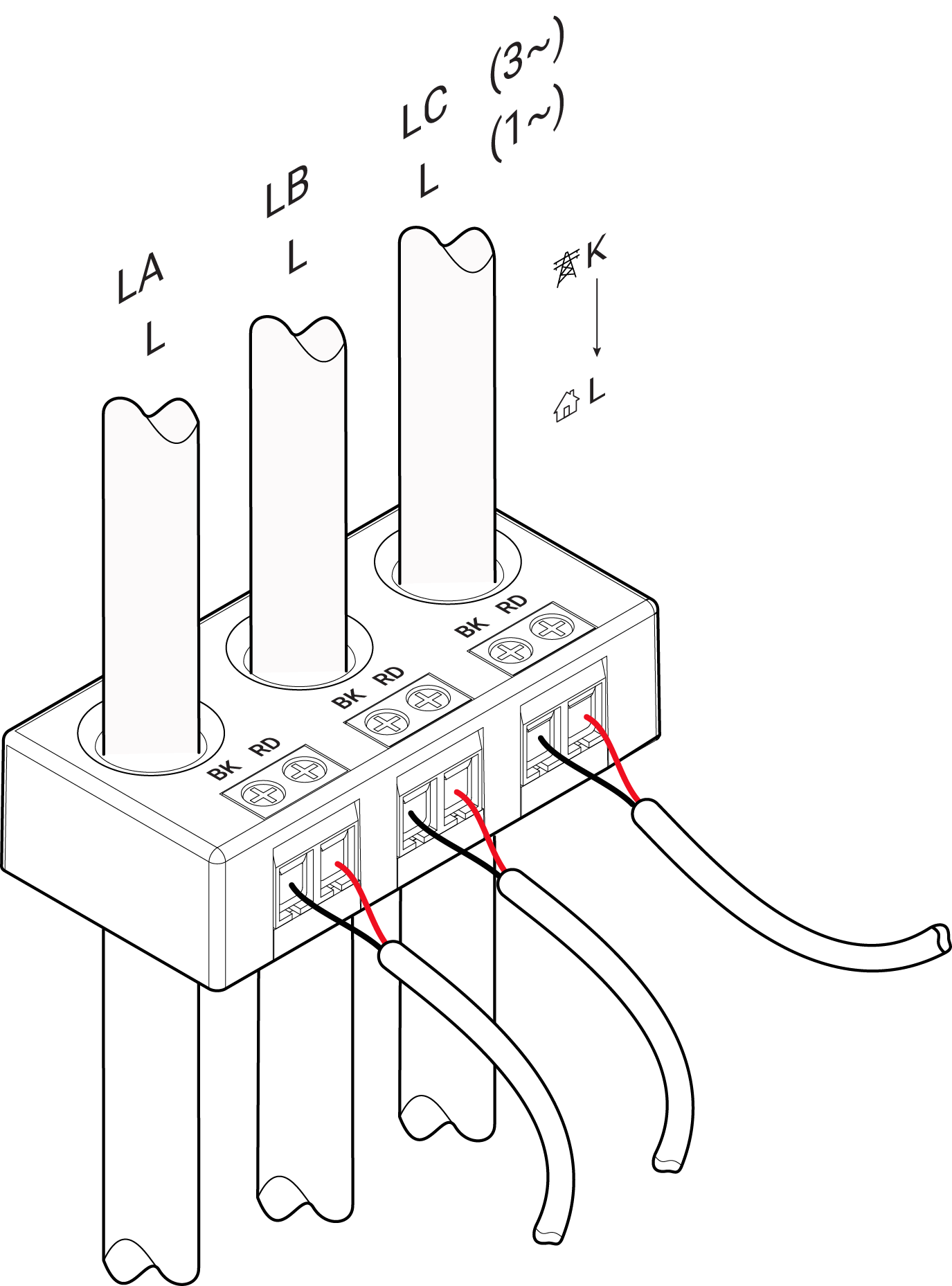
Legend
Enlarges the table by opening it in a full screen dialog
LA, LB, LC: | Three-phase setup (3~) |
L: | Single-phase setup (1~) |
RD: | Red wire |
BK: | Black wire |
K ->L: | Direction of the primary current flow |


