
Main applications
Residential
MDU (Multi Dwelling Units – apartments, condominiums, hotels, etc.)
Light commercial (small office buildings, small retail/restaurant/gas station, etc.)
Agricultural (farms, barns, silos, etc.)
Government/municipal
University/college
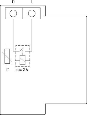
Simplified internal schematics
Device electrical interfaces
Inputs1 load circuit input IOutputs1 load circuit output O Add-on interfaceShelly proprietary serial interface⚠CAUTION! High voltage on the add-on interface when the Device is powered!
Safety features
Internal temperature sensing and reporting
Supported load types
Resistive (incandescent bulbs, small heating devices)
Capacitive (LED light drivers, capacitor banks, electronic equipment)
Inductive (contactors, transformers, fans, refrigerators)
User interface
Outputs
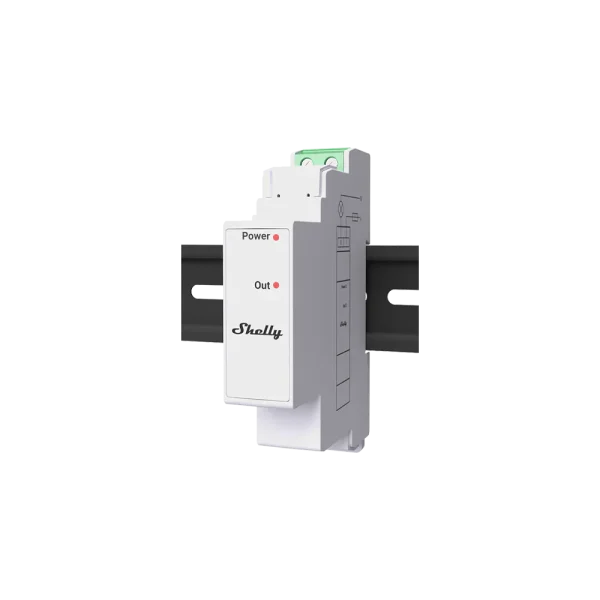
LED indication
Power: Red light if the power supply is connected.
Out: Red light if the output relay contact is closed.
Specifications
Enlarges the table by opening it in a full screen dialog
Type | Value |
|---|---|
Physical | |
Size (HxWxD): | 94x19x69 ±0.5 mm / 3.70×0.75×2.71 ±0.02 in |
Weight: | 20 ±1 g / 0.70 ±0.05 oz |
Mounting: | DIN rail, attached to a Shelly Pro 3EM |
Screw terminals max torque: | 0.4 Nm / 4.43 lbin |
Conductor cross section: | 0.5 to 2.5 mm² / 20 to 14 AWG (solid, stranded and bootlace lugs) |
Conductor stripped length: | 6 to 7 mm / 0.24 to 0.28 in |
Shell material: | Plastic |
Color: | White |
Environmental | |
Ambient temperature: | -20 °C to 40 °C / -5 °F to 105 °F |
Humidity: | 30 % to 70 % RH |
Max. altitude: | 2000 m / 6562 ft |
Electrical | |
Power supply voltage AC: | N/A |
Power supply voltage DC: | 3.3 V and 12 V (from Shelly Pro 3EM device) |
Power consumption: | < 1 W |
Sensors, meters | |
Internal-temperature sensor: | Yes |
Output circuits ratings | |
Max switching voltage AC: | 240 V |
Max switching voltage DC: | 30 V |
Max switching current AC: | 2 A |
Max switching current DC: | 2 A |
Basic wiring diagrams
Enlarges the table by opening it in a full screen dialog
Resistive load |
Inductive load and RC snubber |
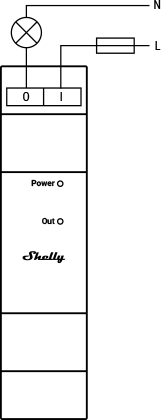
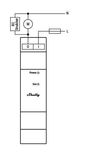
Legend
Enlarges the table by opening it in a full screen dialog
Terminals | Wires | ||
|---|---|---|---|
O | Load circuit output terminal | L | Live (110-240 V) wire |
I | Load circuit input terminal | N | Neutral wire |